
Embedded Systems / F&S Boards
Board Preparation
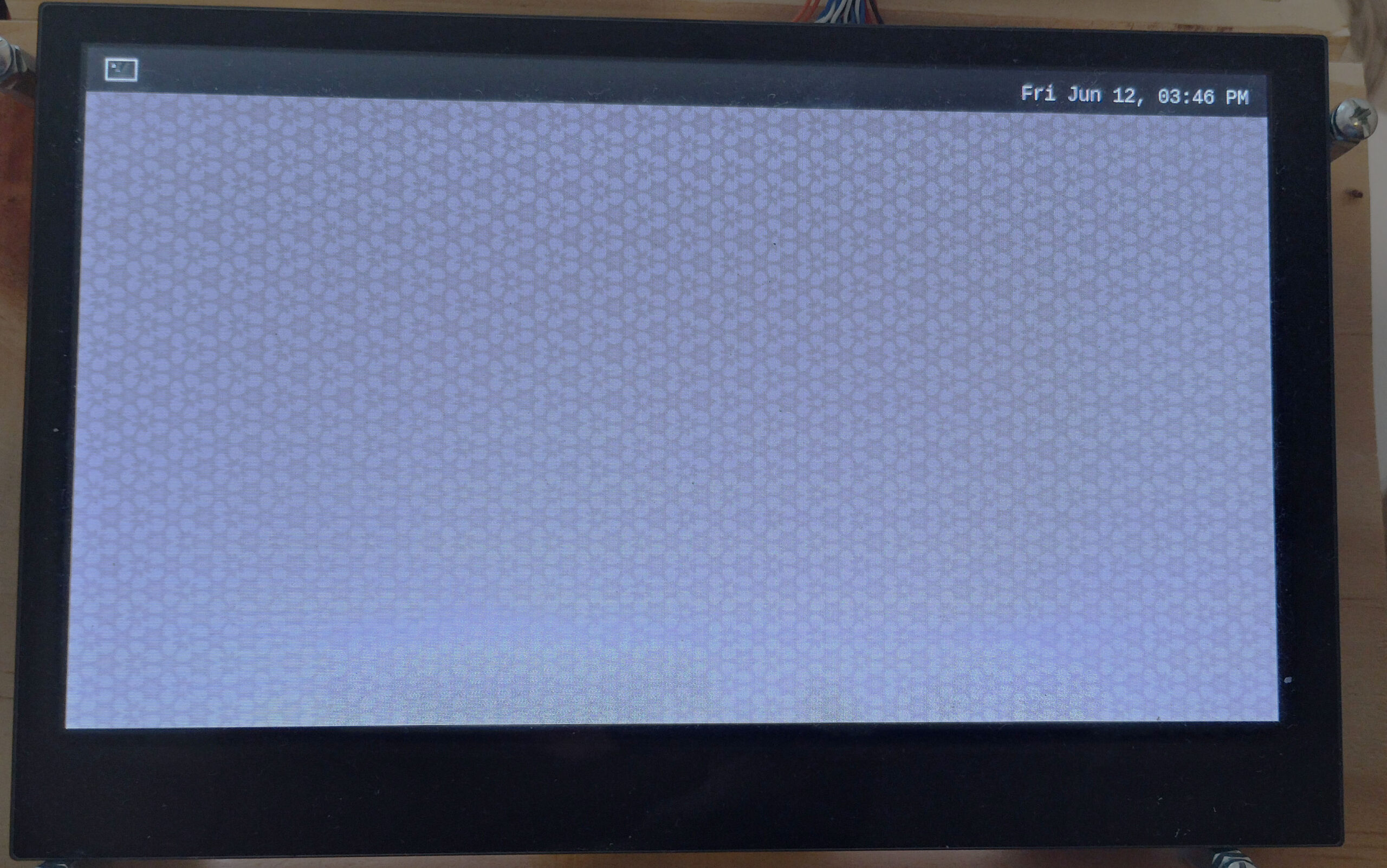
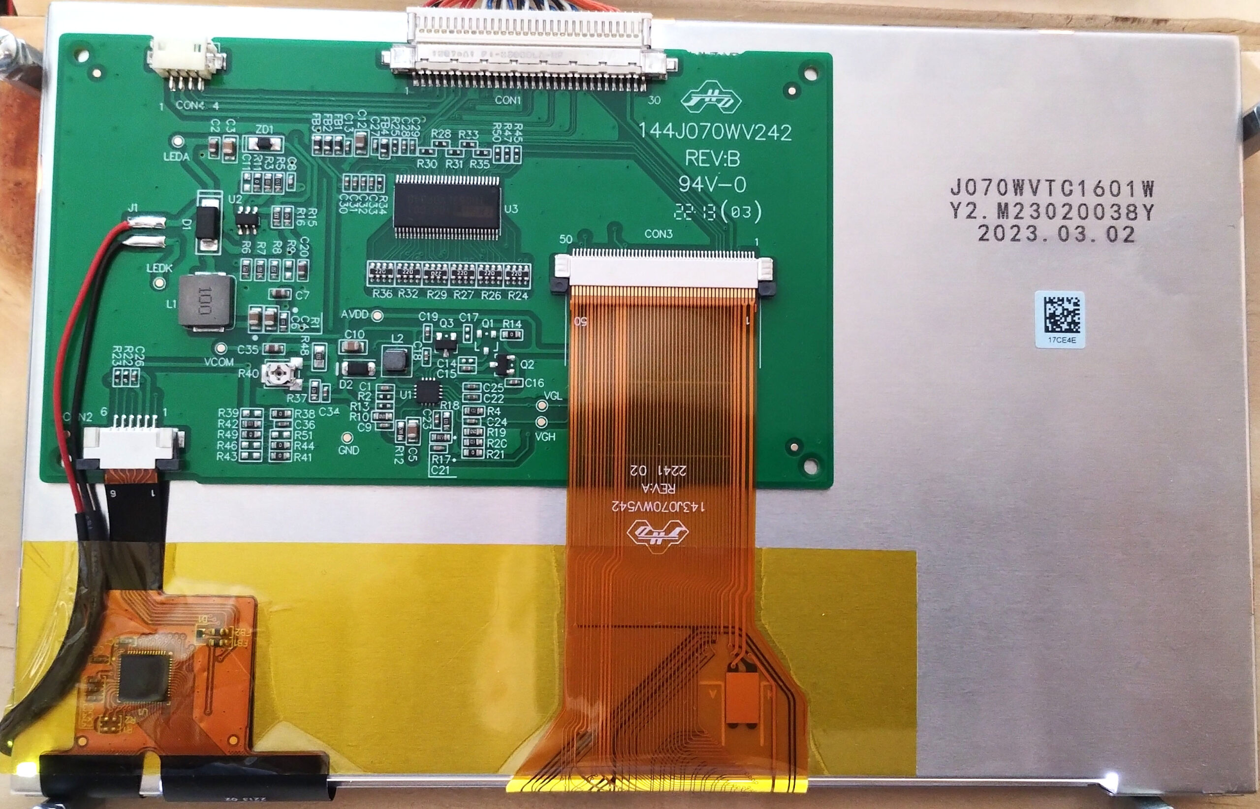
Display Unit
In this setup, we will use LVDS connector-based display unit: J070WVTC1601W
Required
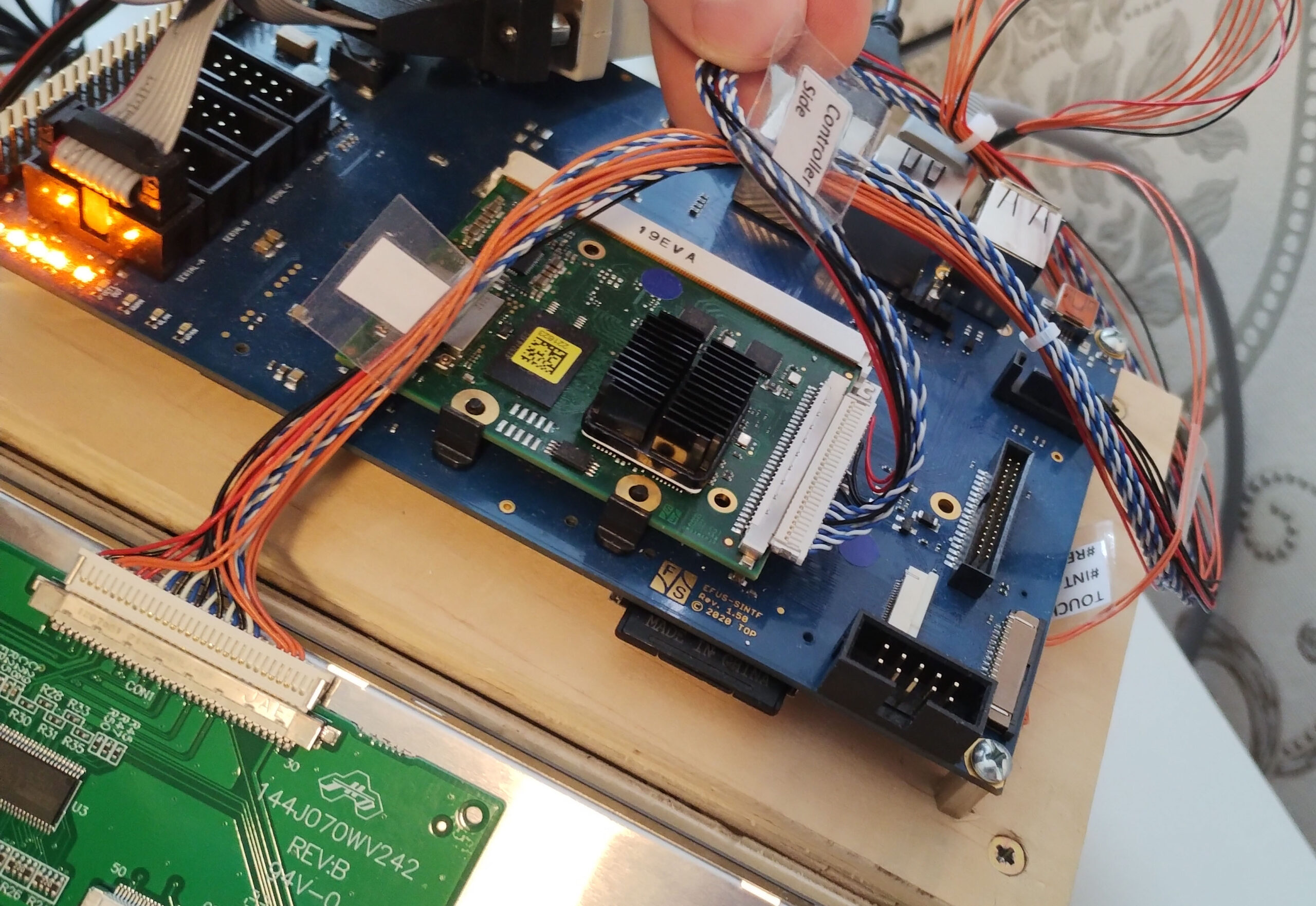
LVDS Display Cable
A cable connector to connect the efus MX8MP chip to the display unit.
Required
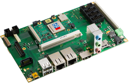
efus MX8MP base board
A base board which provides peripheral connectors to efus MX8MP chip.
Required
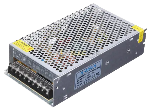
Power Supply
A suitable power source for the board. Use the specification recommended by F&S to avoid unstable behavior during development.
Required
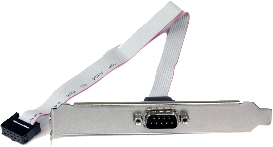
COM / Serial Cable
Needed for serial console access, debugging, and monitoring boot output during board bring-up and operating system deployment.
Required
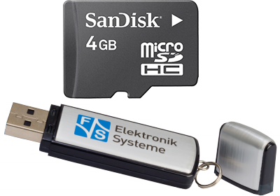
Micro SD Card or USB Storage
Used for image storage, boot media, or file transfer depending on the selected board setup and deployment workflow.
Required
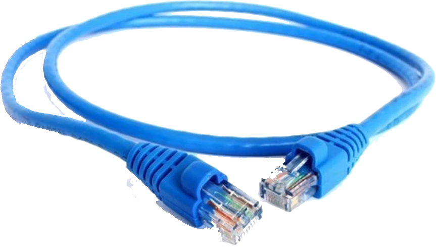
LAN Cable
Provides network connectivity for system setup, deployment, package access, remote communication, and testing.
Required
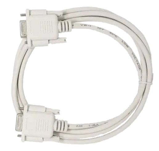
Serial Cable
Connects your efus MX8MP board to your development computer over serial link interface.
Required
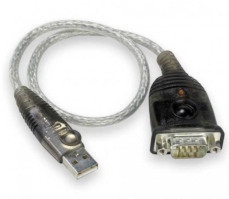
USB to serial adaptor
Most modern PCs are not equipped with serial interface. If that’s your case, you will need an adaptor.
Optional

USB Mouse
Helpful for user-interface interaction and validation when the board is connected to a display.
Optional
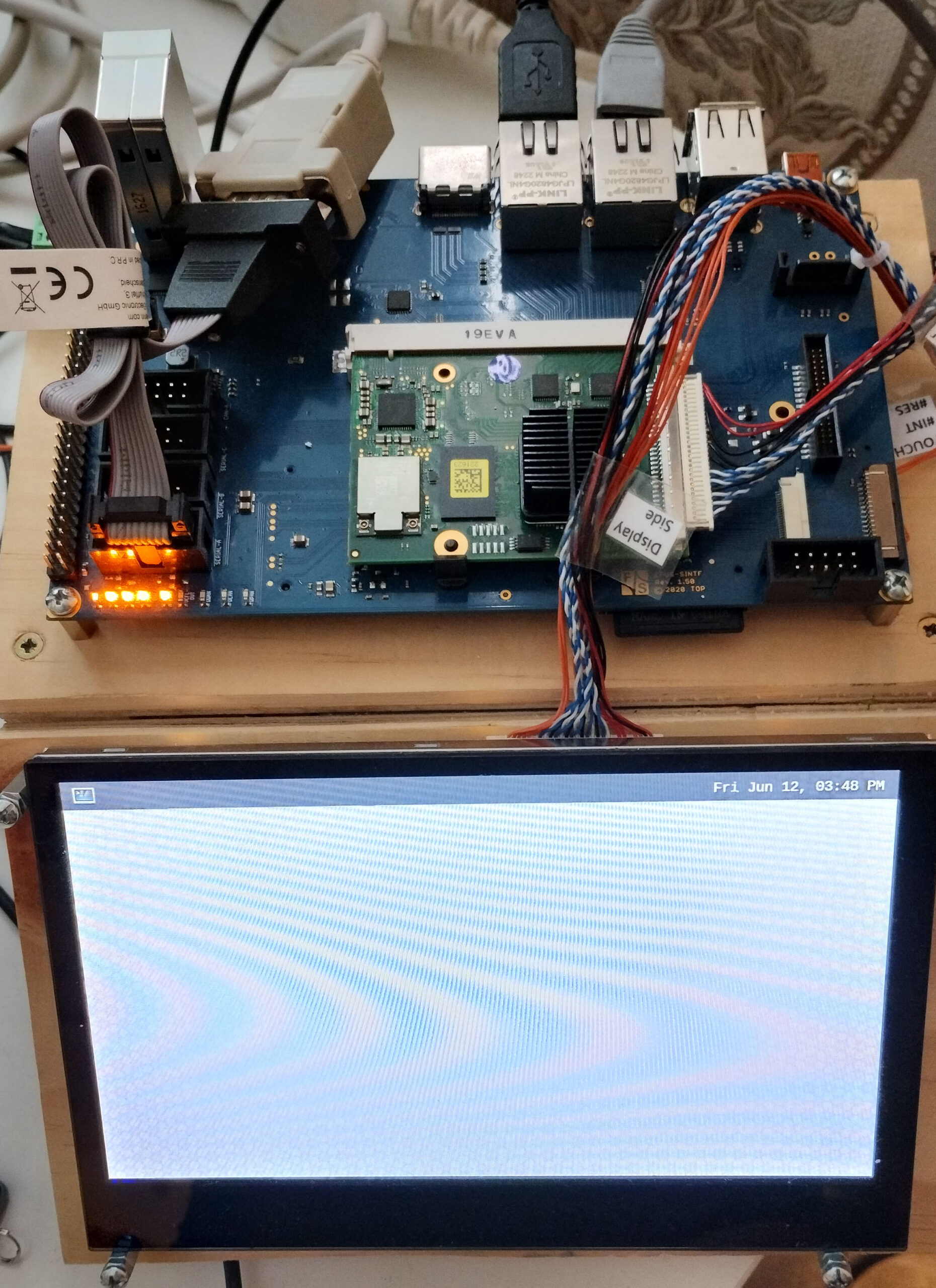
Booting the board
Once you have the entire board set up and all peripherals connected, turn it on by applying voltage from power supply to its input connector. At the same time, make sure that it is connected to your host PC over serial cable.
- Download PUTTY Go to PUTTY download page. Look for putty.exe. Download the correct executable for your processor architecture.
- Start puttye.exe
- A “PuTTY Configuration” windows will appears. Choose Serial under “Connection type:”.
- Type your COM port number into “Serial line” textbox (e.g., “COM3”). If you don’t know it, the click on Windows Start button. Type “Device Manager” and run Device Manager. Look for “Ports (COM & LPT)”. Expand it. Look for your “USB Serial Port …” item. You should see the COM port number there. For example, it may be “COM3”.
- Back in PuTTY window, type “115200” into Speed textbox.
- Click “Open” button.
- A blank “COM3 – PuTTY” screen should appear.
- Hit <ENTER&;gt; key into that windows.
- A login prompt from your fsimx8mp board should appear asking you to type login. If it does, your board is functional, operating and ready to be used.
- Type root as username.
- No password is required by default. You should be logged into the command prompt.